
|
High capacity load testing of generators, UPS, and other AC power sources; periodic reliability exercise of standby generators; automatic load leveling and minimum load regulation; regenerative/reverse power protection and other load bank applications is possible with the Simplex Saturn Version 2.0 Load Bank Series.
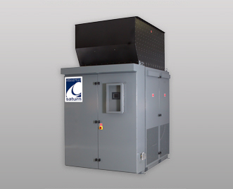
The Simplex Saturn Version 2.0 is a highly standardized, advanced design, digitally controlled Load Bank Series spanning the 1400-3200kw range at common 60 Hertz and 50 Hertz low voltages. Saturn V2.0 Is a standard inventory item with versatile control and application possibilities.
Saturn V2.0 is intended for outdoor or indoor installation. As with all Simplex Planet Series Load Banks, the Saturn is UL/CUL Listed.
|
General
| • | Completely self-contained, freestanding unit which includes all resistive load elements, load control devices, load element branch circuit fuse protection, main load bus and terminals, cooling system, control power supply, unit controller and malfunction detection system and NEMA type enclosure. |
| • | Highly standardized inventory item designed for quick turn-around. |
| • | Supported by nationwide service centers. |
| • |  |
| • | UL File Number: E151624. |
| • | Can be used to satisfy the requirements of the National Fire Protection Association (NFPA) for emergency stand-by power systems. |
System Controls
| • | Digitally controlled via an on-board PLC, which accepts standard programs for manual, automatic and multi-station control, as well as data monitoring and data acquisition. Designed for local or remote control, including multi-station control, using a standard digital, color touchscreen HMI. Remote control connection is simplified through use of RS-485 over shielded/twisted pair network cable (1000m). Local/remote HMI is housed in a weather/tamper resistant, lockable enclosure. |
| • | Manual control via direct numeric keypad entry is standard. |
| • | Option available for automatic load regulation via KW sensing to maintain a constant load on the generator. Load level, bandwidth, and timing are user programmable from the touchscreen. This function can be used for minimum loading to prevent wet-stacking and other low load issues, engine optimum loading for emissions control and for regenerative power protection. May also be used to stabilize voltage and frequency transients. With the automation option, full display of load bank electrical values (V-A-Hz-KW) is provided on the touchscreen, with MODBUS registers provided for remote indication and data acquisition. |
| • | Option available for Load Bank integration with Building Automation Systems via Modbus RTU RS-485 or Modbus TCP. |
Load Elements
| • | Elements mounted in easily accessible, slide out trays. |
| • | Simplex Powr-Web chromium alloy, open wire, continuously supported, power resistor. |
| • | UL Recognized |
Element Circuit Protection
| • | Branch circuit fuses, each 50KW branch circuit, 200kAIC, current limiting type. |
Cooling
| • | Integral forced air cooling system. |
| • | 3-phase, direct drive motor driving cast aluminum fan blade. |
| • | Circuit breaker combination motor starter. |
| • | Rain shedding exhaust hood. |
| • | Cooling airflow through the enclosure is vertical with cold air intake at the bottom and hot air exhaust out the top. |
System Protection / Malfunction Detection
| • | Fan failure, high exhaust temperature, high intake temperature; lockout and alarm. |
| • | Exhaust temperature indicated on screen. |
| • | Load Circuit Protection: branch circuit fuses. One set of fuses each 50KW branch. Fuses are current limiting type, 200,000 AIC, 600V, enabling safe use on large generating or UPS system. |
Load Control
| • | Branch circuit contactors each step, overall 50KW circuit maximum. |
| • | Contactors with enclosed silver surfaced contacts, 120V coils; electrically operated and electrically held. |
Power Wiring
| • | 150°C, color-coded, numbered. |
Control Wiring
| • | 105°C, color coded, numbered. |
Power Connection
| • | Plated bus bar within an oversize terminal junction box. |
Enclosure
| • | Modular enclosure consists of three parts: power section, control section, and exhaust hood. |
| • | Type 3R weatherproof power section includes load elements and cooling fan. |
| • | Type 3R weatherproof control section is thermally and electrically isolated from resistive load power section. |
| • | The rain shedding exhaust hood mounts on the top of the power section. The exhaust hood may be deleted and a duct flange provided for indoor applications where air is exhausted through a duct to the outdoors. |
| • | The load bank enclosure is of double wall construction for cool exterior. |
| • | All access via hinged doors with lockable latches. |
| • | All exterior fasteners are stainless steel. |
| • | Intake and exhaust openings are screened. |
| • | Enclosure is powder-coated dark gray. |
| • | Exhaust hood is powder-coated high temperature black. |
| Capacity |
1400KW, 1500KW, 1600KW, 1700KW, 1800KW, 2000KW, 2250KW, 2500KW, 3000KW, 3200KW |
| Voltage |
All common 3-phase 60, 50 Hz voltages:
60 Hertz: 208V, 220V, 240V, 416V, 440V, 450V, 460V, 480V, 575V,
600V
50 Hertz: 190V, 200V, 208V, 380V, 400V, 416V |
| Frequency |
60, 50 Hertz |
| Load Steps |
25 KW resolution standard. (25-25-50-100-100-250... KW) |
| Duty Cycle |
Continuous |
| Temperature |
120°F maximum ambient temperature
Exhaust rise: 150°F - 200°F
Hot spots: 575°F |
| Airflow |
60,000 CFM, 30-HP |
| Fan/Control Power |
External or internal from load bus. Control circuits at 120V via transformer. The cooling fan operates at 3-phase line voltage. Load control circuits and fan motor control operate at 120V. Control circuits are fused. Control circuit fuses are 100,000 A.I.C., 600V rated. External, 120V, supply for humidity controller, when ordered. |
| Dimensions |
76"W x 136"H x 95"D - height includes 42" exhaust hood |
| Weight |
6140 lbs - includes exhaust hood |
Note: Dimensions and weights are approximate and subject to change with capacities and options selected.
System Controls
| • | Automation option for Auto-Load Regulation, Regenerative Power Protection, via KW sensing. Requires installation of remote current transformer (supplied). User programmable: set point, step up/step down bandwidth, initiate delay, step-up delay, step-down delay, shutdown delay. Includes voltage and frequency sensing with adjustable set point and delay. Includes display of volts-amps-hertz-kw and MODBUS registers for same. |
| • | BMS control. Allows load bank to be controlled/monitored by BMS. |
| • | MODBUS TCP. Replaces MODBUS RTU-485 with TCP capability. |
| • | Multiple remote control stations. |
Fan/Control Power
Malfunction Protections
| • | Main load disconnect breaker or fused disconnect switch. |
Connections
| • | Connection via cable in conduit, cable tray, cable duct, bus duct. |
Enclosure
| • | Indoor configuration. |
| • | Sound attenuation. |
| • | Anti-condensation heaters with thermostatic control. |
Highway Trailer
| • | Trailer construction conforms to applicable Federal and DOT standards. Includes: safety chains, electric lights, electric brakes, leaf springs, ball hitch coupler, lift jack and caster. |
Note: We are experts at building products that meet our customer's exact requirements. Contact Simplex if your job specifications require additional options or considerations.
|
